Though this is not actually part of my train layout, it is very much a model and close to HO scale.
When my paternal grandfather passed away in 1975, I said I would like to have ‘The Lighthouse’.
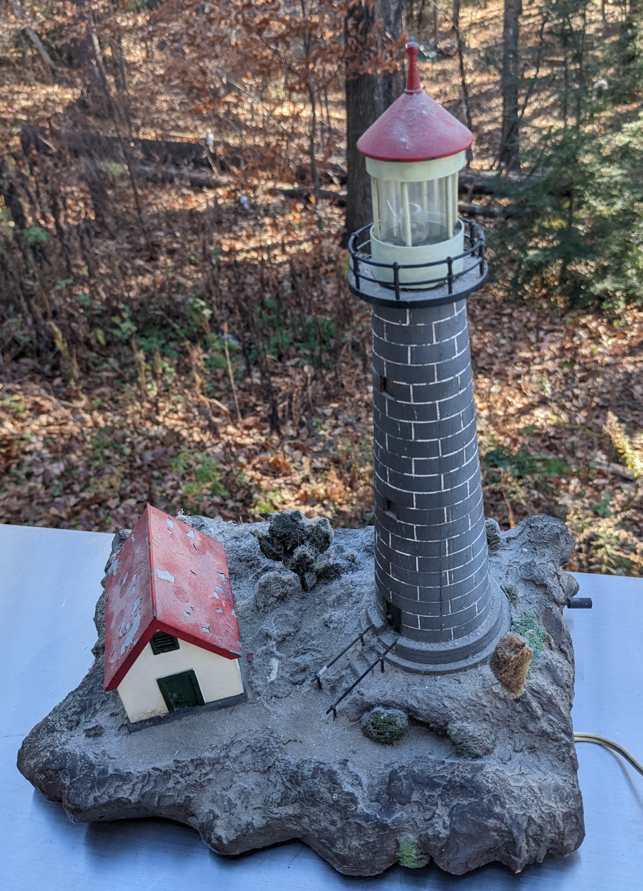
This was a model lighthouse that he had made, many years before, possibly in the 1950s or 1960s, and it used to sit on their mantelpiece in their living room. Standing about 29cm high it includes some rocky terrain and a small lighthouse keeper's house. The magic thing was that one could pull a small shaft on the side and the shed and tower would light up, the lighthouse lantern room light would go on and off periodically. I recall that it simulated the occluding type, meaning it was off for a longer period than it was on.
It was agreed I may have the lighthouse and so it has been with me for more than 4 decades slowly gathering additional layers of dust from Westville, Durban, New Germany, Munich, Chelmsford and now Limerick. I had not run it since 1993 as it was wired for 240 Volts and I did not want to cause any harm trying to run it at 120V even though a lower voltage was less likely to cause harm. I decided it was time to clean it up and bring its electrical innards up to date.
The wiring was very old school, with fabric insulation on the 240 V wires. Wires were held in place with strips of thin leather held in place with a tack. The shaft used to switch it on and off is a hand crafted switch.

I remember the days when insulation tape was a cloth-like material that stayed in place.

When dismantling it, I reached for my wire strippers to help pull the tacks out, which did the trick very nicely. I then suddenly realized that my wire strippers also came to me from my grandfather in 1975, and that very tool may well have been used when doing the original wiring!
The 240V AC current went through his home-made switch, then split off to go into the tower and to a transformer in the little house. He was an armature winder so I think he probably made and wound the transformer himself. A secondary winding powered the small light bulb mounted on top of the transformer, and also a pair of wires went off to the tower to power the light in the lantern room at the top. It was still a mystery how the switching of the light was done and I assumed that there was a bi-metallic strip somewhere that would heat up and break the circuit.
I removed three nuts from some threaded rods that held the tower down to find a large cylindrical mechanism embedded in the base of the tower.

After more unscrewing I was able to remove a device marked:
Sangamo Motor Unit
Mode S. 7
200/250V 50 ~
Pat. 377696 Pat. 384880
2 Revs per hour
The two patents were issued in Britain 1931 and 1932 to the Sangamo Electric Co.
This is a high quality electric clock motor. My grandfather modified the motor by removing the drive shaft and adding some contacts inside in order to make a timer switch! So, there was no bimetallic strip at all, rather, an excellent, very nice clock motor.
The tower is turned from three oak planks that had been laminated together.
I decided that the flaking paint on the roof of the little building should be redone, so I scraped it and repainted it.


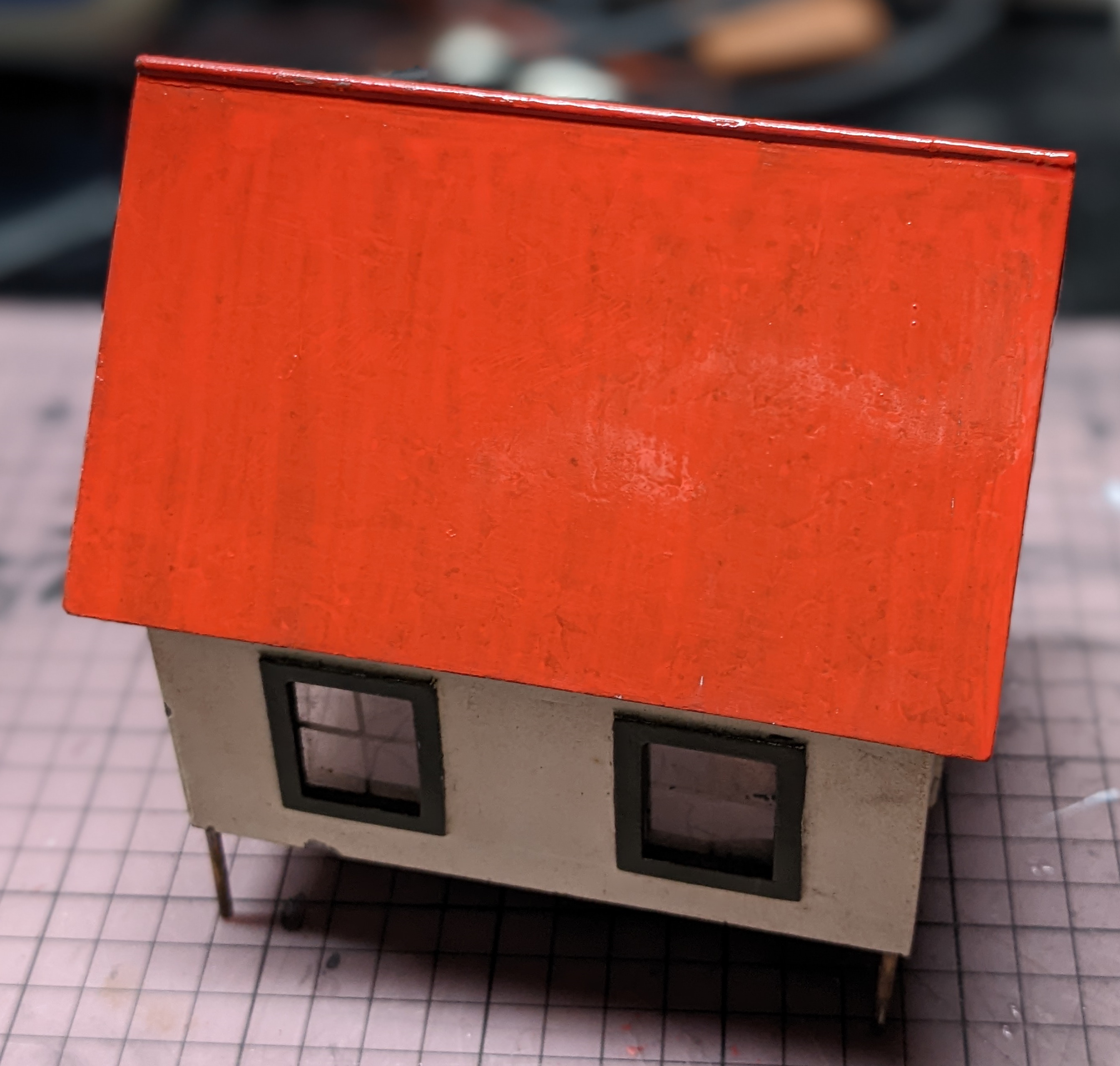
Light has always leaked out the bottom of the front wall of the house, so I added some strips of black paper to block that.
I gave the terrain, and even the bushes, a scrub with a toothbrush and some water and it cleaned up nicely.

In order to mount the large LED I had, I drew a small adaptor part and printed it on my 3D printer.

It fits into the hole of the old lamp holder and has two holes for the LED legs. The length places the LED in the middle of the lantern room.


Replacing the electronics was relatively easy. I recently created a system to 3D print small circuit boards, so I printed one small enough to fit in the building.

The new wires were all stripped using his old wire strippers!

The lighthouse now connects to our network via Wi-Fi and can be controlled remotely. The flashing pattern of the lighthouse as well as the building light and TV flicker can all be independently controlled.
I have also written a small program to fetch weather forecast data and it relays commands to perform different flashing patterns for clear, snow, rain and fog conditions as follows:
Clear weather
The light is on for 2s, and off for 8s, from 30 minutes before sunset through to 30 minutes after sunrise. During the day, it is off unless there is rain, snow or fog.
Rain
During, and 30 minutes before the rain is predicted, it will be on for 3s, off for 3s, day or night.
Snow
During, and 30 minutes before the snow is predicted, it will be on for 8s, off for 2s, day or night.
Fog
During, and 30 minutes before the fog, mist or smoke is predicted, it will be on for 5s, off for 5s, day or night.