Showing posts with label lighting. Show all posts

2023-12-31

Upgrading the Märklin 7286 turntable

My Märklin 7286 turntable was not moving so it was long overdue for a service. While I did that, I also decided to do some upgrades to make it work better than before.


I describe here how I carried out the following upgrades:

  • Improved rotation
  • Improved electrical contacts
  • Added lighting to the control shed
  • Added control desk direction indicators
  • Added an operator in the control shed


    Improved rotation

    The turntable was designed to work with analog layouts. Track power is provided to the running rails and the center rail from below, and there are contacts at both ends of the bridge to transfer this power to the current spoke track. This allows one to only power the spoke track one is using, allowing locomotives to be left on other tracks unpowered. On a digital layout, all the tracks can be powered all the time, making all these contacts superfluous. Not only do these contacts add resistance to the rotational movement, they also make clicking noises and they even cause short circuits between the center rail contact  and the running rails of the spokes. I had previous defeated the connectors around the edge of the turntable by jamming them in. I decided it was time to take it a step further..

    The center rail on the turntable has two metal plates that lie between the running rails. I cut the ends off both with hacksaw, filed them smooth and painted the ends black.


    On the underside of the bridge, at the end of each rail was a small contact. I cut all four off with some small side cutters:

    This results in a much smoother and quieter rotation.

    Electrical contacts

    The turntable bridge pivots about on a central support ("Königsstuhl") which has some concentric contacts. These contacts needed cleaning so I rubbed them with a very fine sandpaper and also cleaned them with some contact spray applied with a cloth.


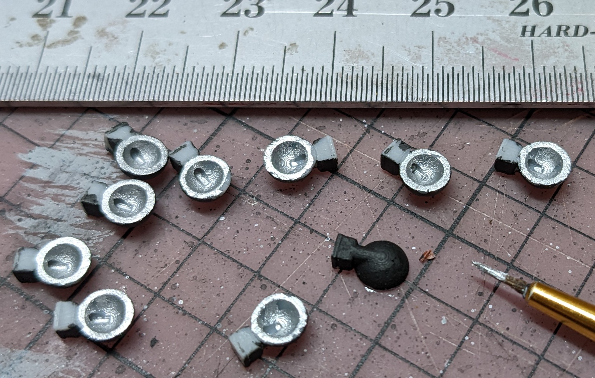
    I also cleaned the finger contacts on the underside of the bridge that ride along on the contacts:


    Despite good contact on the supporting side, I could not get one of the running rail contacts to work, despite bending the finger downwards to apply more pressure, so I gave up and soldered a wire between the two rails.


    Control shed

    It always annoyed me that there was no light in the control room, so it was time to fix that. The shed unclips from the bridge providing good access to the interior. The glass windows are made from a single translucent piece that has a small dimple in the ceiling, a perfect size for adding a surface mount LED.

    First I looked closely at the LED with a magnifier to determine which wire was connected to the end with a small dot. This is the side that has to be connected to negative. I tied a small knot in the other end of that wire.

    I taped the LED into the top and ran the fine wires to the the corner of the building .


    I then inserted the glass into the shed, keeping the wires between the glass and the outer frame at the corner so they cannot be seen.


    There is enough room in the hole that the building clips into, to pass the two wires through to the underside of the bridge without having to drill a hole.


    I decided to power the light using the power from the track as I did not want it only going on when the turntable was moving. Since the track contains the digital signal, it is AC and thus needs a diode to only allow the current to flow in one direction, plus the usual protection resistor.

    The rails provide one side of the power source for the light, so I needed to get power from the center rail. I soldered a wire onto the small contact that conducts the center rail current to the parts between the tracks:


    I drilled a small hole next to where the contact sits:


    and threaded the wire though and soldered it to a 1N4001 diode.

    The other wire was soldered to a 2K Ohm resistor soldered to one of the running rail contacts.

    A quick test showed the light worked well.


    Control desk direction indicators

    I thought it would be nice to put red and green LEDs into the control desk so that when the bridge moved one way, a green light would go on, and the red LED would indicate the other direction.

    I drilled a very small hole in the middle of the control desk.


    I then connected the two LEDs in antiparallel. (I did not have a green SMD LED so I used a red SMD and a much bigger green one)

    This illuminates the red LED when the current flows in one direction, and the green LED when the polarity is reversed. These were then inserted into the hole on the underside and one side was soldered onto a 2K Ohm resistor.


    The pair of LEDs then had to be connected to the motor terminals, so that red will indicate one direction and green the other. One motor terminal is easy to connect to, but the other required a contact to be temporarily removed to solder a wire on.


    It works:


    however, the control room light is too bright for them to show up well. I need to increase the size of the resistor on the room light.

    Operator in the control shed

    I found a person that looked suitable and glued him in front of the control desk.


    2022-11-07

    3D printed LED exterior light

    While assembling a plastic building, I decided it would look much better if the exterior lights actually worked, so I set about designing some exterior lights.

    I used OpenSCAD to design a half hemispherical shade (5mm diameter) with a small wall mount. A 1mm diameter hole allows for the wiring of a surface mount 0402 LED. After three 3D printing iterations I ended up with a usable design.

    I painted the inside with silver acrylic paint, and threaded an LED in to test it out.


    As expected, there was a lot of back scatter of the light, so I decided to paint the top black.


    At this stage they look rather like toilets.

    I threaded in the LEDs. In order to keep the LED facing the right way I found I had to tape the wires to the work surface.


    I then added a drop of super glue to each LED and let them dry.

    To add them to the building, I drill a small hole with a pin vice.

    After threading the wires through the wall I could see that a second coat of black paint was in order to ensure complete coverage.

    A drop of super glue holds the light in place.

    I will use these on the row of Vollmer buildings I am constructing. I will probably run two 5V power circuits to the buildings, one, always powered, for internal lights and the controller for the butcher shop and the other, switched, for night time when exterior lights are appropriate.

    A 5mm light in HO scale represents a 43.5cm light - a reasonable size. I could probably make them even smaller.

    2020-11-13

    Modelling with LEDs

    Modern modeling uses Light Emitting Diodes (LEDs) extensively. This is because they offer numerous advantages over older technology, such as incandescent 💡 light bulbs:

    • They are small
    • They are cheap
    • They are long lasting
    • They use very little current
    • They do not get hot
    • They are available in many colors (including 'warm' and 'cool' white)
    Unless you are trying to reproduce models as they were in days gone by, you are going to be using LEDs on your models. They are not difficult to use but one does need to learn a few simple rules to use them.

    The aim of this page is to explain the theoretical side of what is needed to power LEDs, how to connect them and even how to produce good results in moving model trains. I will be starting off with some very fundamental principles and building up to powering LED strips from digital power. The actual installation of lights inside building is covered here, this is about what has to be installed.

    LED packages

    LEDs come in a variety of different forms and sizes (called packages in the electronics industry).

    Through-hole

    Typically round 2mm, 3mm, 4mm or 5mm. Rectangular and other shapes are also available.

    3mm & 5MM LEDs
    3mm & 5mm LEDs

     Surface mount (SMT)

    These are even smaller than the through-hole packages and are usually soldered directly to circuit boards by machines. One can now also buy them with tiny wires already attached and these are ideal for model building.

    The different sizes are expressed using a 4 digit code that is made up from the length and width of the LED in tenths of a millimeter. For example a 2835 is 2.8 mm by 3.5mm. 5050 is 5mm x 5mm. Note, however, that some LED sizes are expressed in thousandths of an inch instead, so a 0402 SMD LED is is 1mm x 0.5mm. It is so small, it represents an object 87mm x 43mm in HO scale! - smaller than a lightbulb.

    0402 LED
    An 0402 SMT LED with wires.

      Strips

    White LEDs are also commonly found in long, flexible strips up to 5m (16') long. These are made using surface mount LEDs. They are pre wired and ready for use with 12V (sometimes 24V). One can cut them to small lengths, typically 5cm long. These are ideal for passenger car and station lighting. They often use 5050 or 3528 sized LEDs. They are available in various colors, including warm, and cool white.

    LED strip

    These strips come with a crummy adhesive backing that will not stick for long, and so should be ignored. They need to be attached with a quality double sided tape such as 3M VHB tape.

    Multicolor neopixel etc.

    There are components that comprise 3 (R,G, B) or 4 (RGB+W) LEDs which allows the color of individual LEDs in a string to be digitally controlled independently. These fall out of scope of these fundamental concepts.

    Electricity fundamentals

    In order to understand how to connect LEDs up we do need some very fundamental understanding of electricity. Specifically we need to know a little bit about voltage, current and resistance. It may aid the understanding of these concepts by thinking of electricity rather like water in a pipe. For this analogy:

    • Voltage (V) - think of the Voltage as the pressure/speed of the water in the pipe. Measured in Volts
    • Current (I) - think of the Amperage as the diameter of the pipe. Measured in Amperes (Amps, A or mA. 1A = 1000mA) 
    • Resistance (R) - think of resistance as obstructions to the flow of water in the pipe, such as blockages or mesh grates that slow the water down. Measured in Ohms (Ω)

    These three things have a simple relationship between them: V = I x R (Ohm's Law) and this formula is used to calculate things in all circuits, but fear not, most of the calculations have all been done already.

    Just like a pipe, where water can travel in both directions, so can electricity flow in either direction along a wire. If the pressure is higher at one end, water will flow to the other end. If the voltage is higher at one end of a wire, electricity will flow to the other end of the wire, so long as it can get out.

    Like pipes, larger amounts of current (Amperes) need thicker wires.

    Series and parallel

    We will talk about connecting things in parallel or series, let's just make certain the difference is clear.

    Series connection of two lights
    Series connection

    2019-01-18

    Room lighting with RemoteSign

    After 6 years, I decided to upgrade my layout room lighting so that I could also control it from the layout software.

    I wanted to be able to dim the room lighting automatically so that sunrise and sunset sequences could be done smoothly. Until now I had to manually adjust the dimmers of three lighting circuits which was somewhat tricky.

    Purchasing digitally controlled lighting would have been prohibitively expensive and furthermore I was not prepared to remove the existing LED strips from the ceiling above the layout. I decided to implement digital access to the lighting by adding electronics where the existing lights obtained their power and were controlled by the dimmers.

    I have four circuits:
    • Warm white ceiling lights - drawing about 3.5 Amps at full power.
    • Cool white ceiling lights - drawing about 5 Amps at full power.
    • Mountain backdrop lights  - drawing about 2.7 Amps at full power.
    • Hidden area lighting  - on/off - which draws about 3 Amps.

    I decided to use an ESP8266 NodeMCU processor to control the lights. This is a small processor about 1" x 2" in size and can be bought for less than $5. It is capable of connecting to WiFi and has a number of outputs that can be used for the lighting, but these outputs are only 3.3V and only capable of 12mA, so those logical level outputs had to be fed to some components that amplify the signals and drive the high current load of all the lights.

    I also found some technology called Blynk which includes the ability to easily create an app that runs on mobile devices and can 'talk' to the ESP8266, thus providing a handy visual interface to control the lights. Here is what my Blynk app for the lights looks like:

    2018-02-04

    Philips Hue light control now integrated into my train control software

    I have some Philips Hue lights in my train room and I use them to simulate sunrise, sunset and also the Aurora Borealis in one area of the layout. Until now, I controlled the lighting with a separate program. I decided to incorporate that functionality into my layout control program as events that can be configured to alter the lights in any possible manner.

    Here is my ICE 3 train going past the sunset....


    2017-04-21

    Layout photography

    This page is an attempt to provide some tips on taking decent photographs of your train layout. Some of the original text dates back to September 2006 and I have now updated it in places where the technology has changed.

    Some people have asked how I produce such nice sharp images of my train layout so I thought I would describe the techniques that I use.

    2016-10-30

    Faller B-145 (120145)

    In the 1970s I constructed A Faller B-145 kit - a small BP diesel bowser to fill Diesel locomotives. It was not the best of assemblies and I seem to have preferred putting the roof on top of the roof supports rather than hanging it from it as the instructions suggested.

    I decided it was time to weather it and give it a light 40 years later...

    I put some rust color on the infrastructure and some black mess on the tanks.

    2016-09-27

    Review: Busch HO 2878 Day and Night backdrop

    The Busch backdrop is rather unique in that it is two sided. In addition to the front which depicts the facade of a row of residential houses in a large city, the back is printed with dark ink leaving some of the windows and all the street lights 'clear' so that light can shine through for night scenes. On the right hand end is a field and a boulevard with trees going down to a large church. It is designed to transition from an urban area to farmland. The left end is designed to join onto the Busch HO 2877 product - additional urban buildings.

    Illuminated street

    I describe here the steps I took to mount the BUSCH HO 2878 backdrop on my layout with two sets of lights, the windows and the streetlights. Here is the finished product so one can see the end result that I was aiming for...

    2015-12-07

    The light at the end of the tunnel

    Back in 2007  I unveiled the light at the end of the tunnel in my old layout. Since I was about to complete the mountain on the new layout, I installed the light in the new location.

    2015-03-29

    S88 panel

    I decided to add a length of white LED strip underneath the layout to illuminate the panel where I connect all the track detection wires to the s88 modules. The additional light makes it much better to see when adding a new s88 detection point.

    I try to bring the wire bundles in to different point on the panel and leave ports open for when I use the unused wires in a bundle. This is why some of the s88 modules still have some unused sockets.

    2014-08-12

    LED lighting in the Schattenbahnhof

    Now that I have added the layer above the hidden station (Schattenbahnhof) I have been able to connect the rest of the white LED lighting strip that allows me to see what is going on in there...


    2014-02-14

    Dawn on the farm

    I have now fastened the old farm and mountain road in place in front of the backdrop and connected up the farm house and shed...

    Smell the coffee and listen for the rooster as the farmer starts the tractor...


    2014-02-09

    Backdrop lighting

    I remounted a backdrop from the old layout on the sky wall behind the farm. This time I placed a strip of warm-white LED lights behind the backdrop so that I can simulate a dawn or sunset behind the mountains.

    First I screwed some  ¾" furring strip onto the wall..

    2013-11-06

    Betriebswerk lighting mostly reconnected again

    I have now been able to reconnect most of the lighting in the Betriebswerk.  The big yard lights are dead, not sure if the LEDs have blown or what so they will have to wait for later....


    2013-02-13

    Room lighting with LEDs

    In the time since I prepared the room for my previous layout, LED technology has advanced tremendously. I found however that LED light fittings were rather expensive if one wanted to cover 450 square feet so I looked for an alternative.....

    I found that one can now buy a roll of LED strip lights 5m (16') long and I tried some out, liked the result and then formed a plan to illuminate the layout area with dimmable LED strips.

    2008-01-27

    Water Tower (Faller 120166)

    Before working on the third engine shed, I need to get most of the work done behind where the shed will go so I have installed the water tower (Faller 120166) and done most of the ground preparation.


    2007-10-30

    Converting Märklin 7283 to LED operation

    I decided to convert a Märklin Tower Mast lamp to LED operation and rewire it using much thinner wires than the originals which were pretty thick , bright and unsightly.

    It is a pretty easy operation and the steps were carried out as follows:

    Remove the lamp cover and light bulb.

    2007-10-13

    Winery restaurant at night

    I have now completed the tower and restaurant that is part of the winery. Here are some night time pictures.

    The menu outside is illuminated

    2007-09-01

    Tractor shed with light

    I modified an old Faller kit (289) to create a place for the farmer to park his tractor and store some things such as diesel, oil, etc.