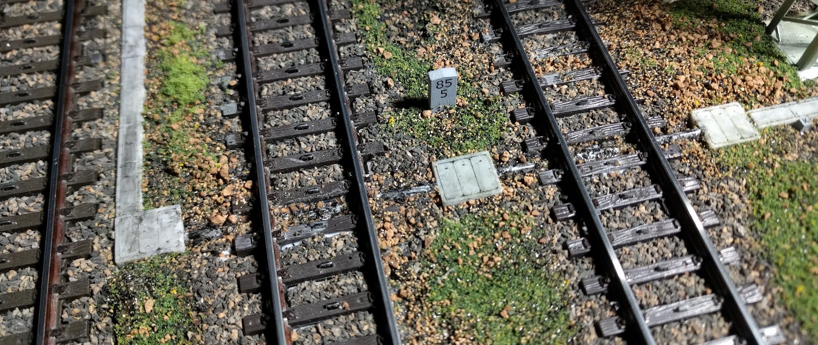
Observe almost any railway track in Europe and you will likely notice a line of cement tiles running all along the track-bed. These are the covers of ducts that carry electrical cables used for running the railway.
I decided I would add some to my layout and set about creating some designs which could be printed on my 3D printer. The first question was, "How big are they?" I spent some hours browsing through the online product catalogs of European manufacturers who specialize in making the ducts and various trackside accessories for the rail industry. They come in almost every size imaginable!
I settled on making ducts 40cm wide, and designed them with gaps between the edges and covers.


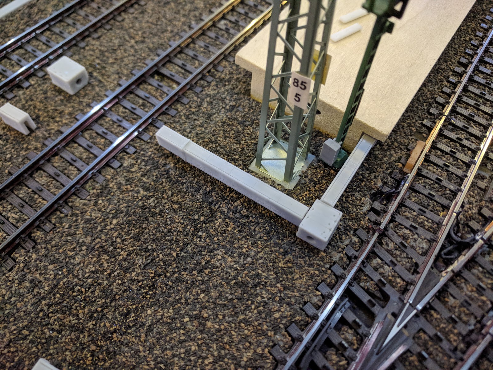
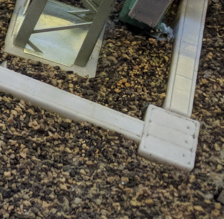
I also knew I needed to have junction boxes

and bends to route the ducts around poles and other obstructions as well as conforming to bends in the tracks. I designed bends for all the Märklin turnout and curve angles.
 |
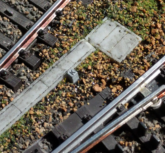
In my internet reading I also came across cable duct markers and it took me a while to find out what they all meant. These markers indicate what is in the duct.
- K = Security and telecommunications
- M = Connection sleeve for type K
- ↯ = Power supply
- C = Condenser sleeves
- P = Pupin coils (Loading coils to increase inductance)
- DR = artificial bend point


What started off as a simple project to make some ducts had now turned into a comprehensive system!
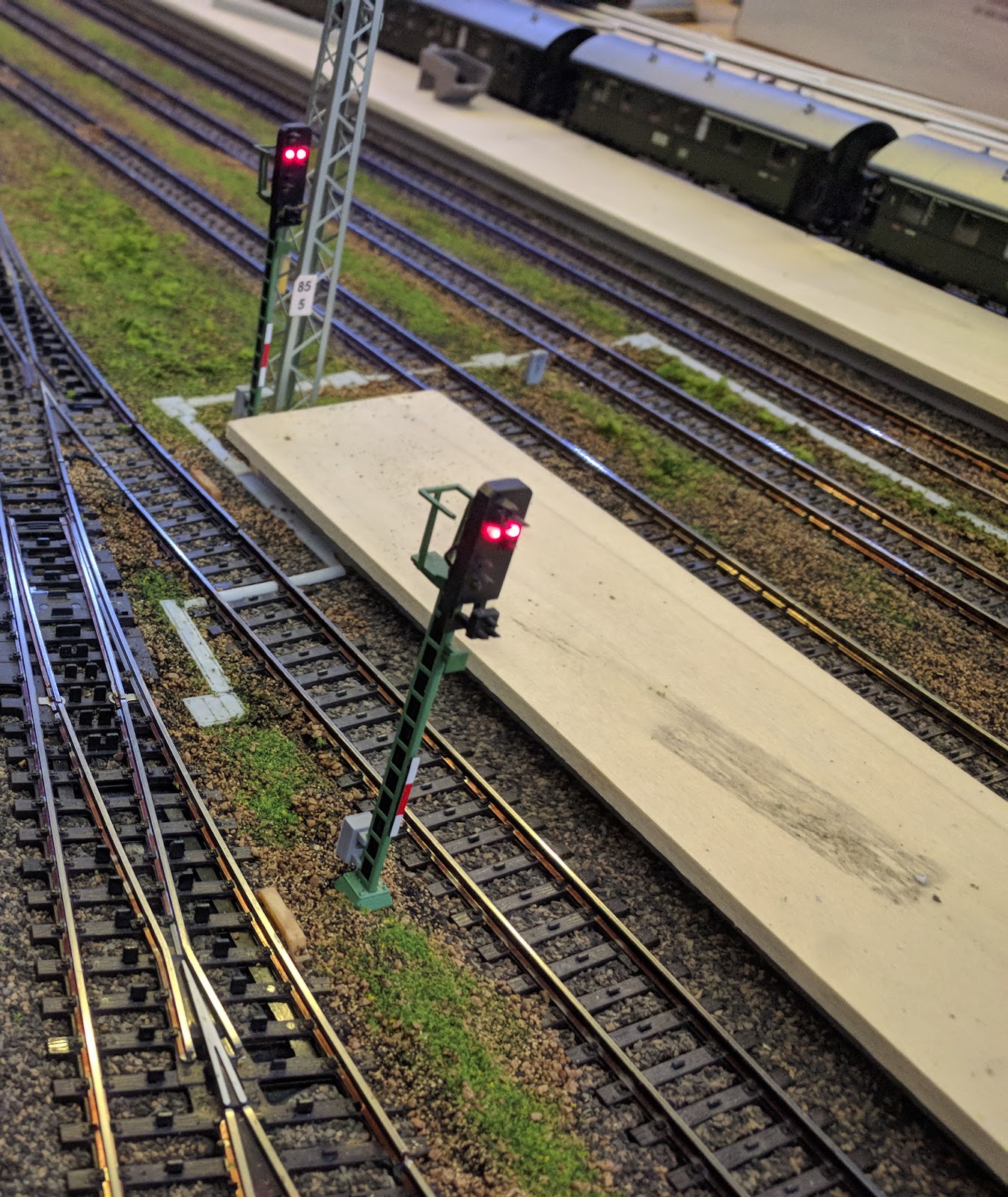
Installation on the layout was not difficult. The first task was to determine the route of the ducts from my signal box to the signals, turnout, and Indusi magnets.
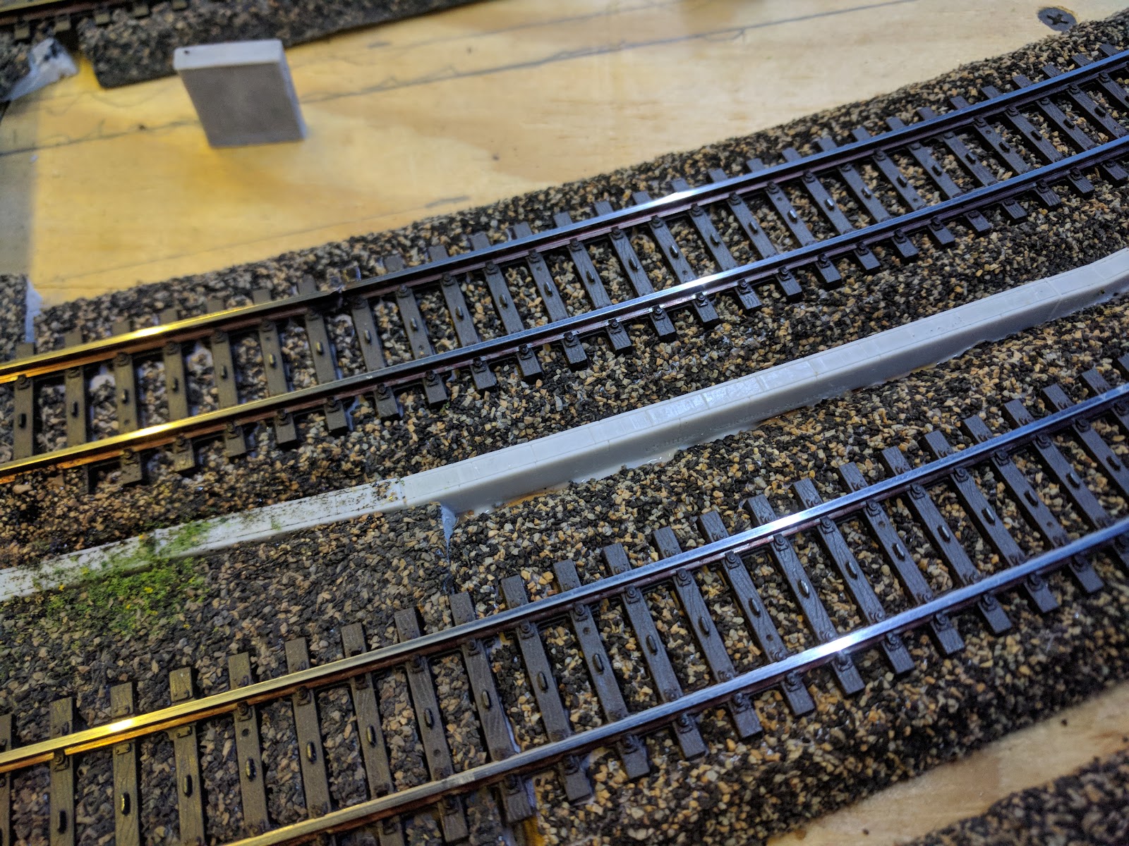
I then decided that it was best to install the junction boxes first, as it is pretty easy to adjust the lengths of the ducts by sanding them shorter. All I had to do was cut a hole in the ballast..
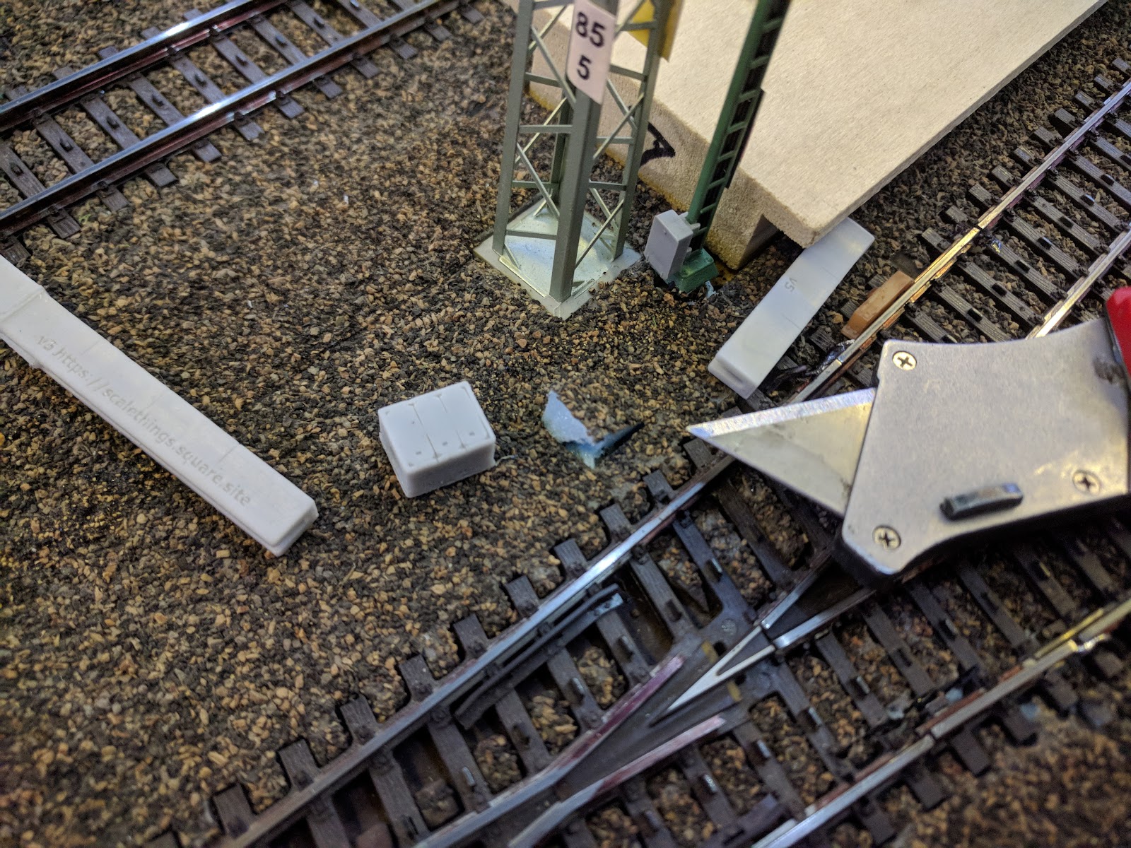
and then push the pieces in.
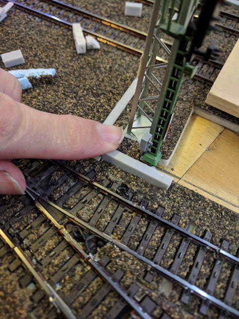
Once I was happy with the positioning, I dipped the pieces into some wood glue and reinserted them.
I found the results encouraging even without any weathering.
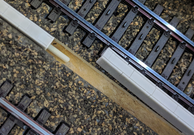
To keep each duct neatly aligned with the adjacent one, I made small alignment tabs.
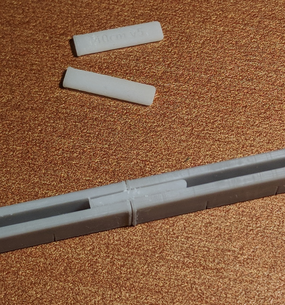
Laying a long run of ducts is a matter of gluing one in with an alignment tab, and then adding the next.
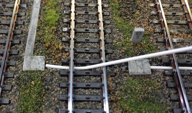
Once the rod had been cut to the right lengths, I glued them down and then weathered everything with some black acrylic paint.