There is a tremendous amount of confusion in the hobby about the nature of the electricity found in model train tracks. This is aimed at explaining the characteristics of the different types..
Before we get into actual trains let's get the terminology straight first.
Alternating current (AC)
From Wikipedia
Alternating current (AC) is an electric current which periodically reverses direction and changes its magnitude continuously with time in contrast to direct current (DC)
The usual waveform of alternating current in most electric power circuits is a sine wave, whose positive half-period corresponds with positive direction of the current and vice versa. In certain applications different waveforms are used, such as triangular waves or square waves. These currents typically alternate at higher frequencies than those used in power transmission.
Direct Current (DC)
From Wikipedia
Direct current (DC) is one-directional flow of electric charge. The electric current flows in a constant direction, distinguishing it from alternating current (AC)
Pulse wave
From Wikipedia
A pulse wave or pulse train is a kind of non-sinusoidal waveform that includes square waves (duty cycle of 50%) and similarly periodic but asymmetrical waves (duty cycles other than 50%).
Digital Cab Control (DCC )
This is the predominant standard digital protocol, and is maintained by the NMRA. The electrical characteristics are defined by NMRA: S-9.1 which defines the signal on the rails as:
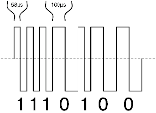
The NMRA baseline digital command control signal consists of a stream of transitions between two equal voltage levels that have opposite polarity.
From Wikipedia
The command station/booster quickly alternates the polarity on the rails, resulting in a modulated pulse wave.
 |
| http://en.wikipedia.org/wiki/Image:DCCsig.png |
Now, let's look at some model train history. There are two ways of supplying current via the tracks to electrical model trains, three-rail and two rail.
- Three-rail systems have an electrical contact between the two outer rails and power is picked up by a slider that runs along the third rail and returns power through the wheels to the two running rails which were electrically connected.
- Two rail systems use both running rails to provide the two electrical poles.
Historically some model train manufacturers, such as Märklin, opted for 3-rail and others, 2-rail.
In addition to the number of electrical rails used, manufacturers needed to choose the nature of the current. Before digital came along there were two analog options AC or DC. Märklin standardized on AC and others went with DC. Both systems controlled the speed of locomotives by varying the voltage of the current. Märklin controllers varied the running speed by varying the AC voltage from zero to 16 VAC and the wave form (at full speed) can be represented as follows:
The wave form of the analog train track voltage was sinusoidal (that wave shape you see above), simply because it was created by transforming mains voltage (sinusoidal 220VAC or 110VAC) to 16VAC.
Changing direction was initially achieved by flipping a switch on the locomotive, and then later by sending a high voltage AC pulse. The pulse actuated a solenoid which switched the wires through the field coils.
DC systems controlled the speed by varying the DC voltage and direction changes were achieved by reversing the polarity so that the motor turned in the opposite direction. Here is a representation of a DC current at a constant speed setting:
The combination of those two decisions resulted in a world where most 3-rail systems used AC current and most 2-rail systems used DC current. This in turn, resulted in many people referring to the two dominant systems as either AC/DC or 3-rail/2rail through association. It is quite possible to have a 2-rail AC system and a 3-rail DC system.
The upshot of this nomenclature is that many people now think that any 3-rail system is AC and that 2-rail systems are DC. That was not much of a problem until digital control came along.
As can be seen by the definitions of AC and the NMRA DCC specification, there is no other logical conclusion other than the fact that DCC is a type of alternating current. The current alternates polarity rapidly, which is what defines AC current. The DCC signal is not sinusoidal, but as is clear from the Wikipedia definition, AC current is not limited to being sinusoidal.
Here are three different AC waveforms:


 |
http://en.wikipedia.org/wiki/Image:DCCsig.png
|
Now that all describes the nature of the current in the rails. When a digital locomotive gets a digital signal from the track, it feeds that into a digital decoder. The decoder decodes the information in the voltage polarity oscillations into data that it uses to decide if it needs to do anything (such as go faster/ stop/ turn on lights etc.) and it also converts (rectifies) that alternating current into a DC current. In addition to powering the decoder itself, the DC current is also fed to lights, and (usually) the motor with the polarity matching the desired direction of travel. The speed of the loco is governed by pulsing the DC current on and off at different ratios. This is called Pulse Width Modulation (PWM).
Modern decoders prefer using DC to drive the motor for two main reasons:
- It is backward compatible with DC motors found in analog locomotives as well as universal AC motors.
- It allows load control using back EMF - essentially it is able to get feedback from a DC motor to determine how fast the motor is turning.
This means that if one is converting an analog AC locomotive to use a modern decoder, it is best to convert the universal AC motor to a pure DC motor. This is achieved by replacing the field coils with a permanent magnet.
So, if you have been fully following along, a modern digital locomotive is picking up an AC digital pulse wave from the tracks and sending PWM DC power to the motor.
This is why referring to a locomotive as either AC or DC can be confusing. 'AC' could (sloppily) refer to 3-rail, or the form of the track current or the nature of the motor in the loco.
Multimeters
People who have digital systems sometimes try to debug a problem by measuring the current in the tracks by whipping out their multimeter. Some multimeters demand to be set to either AC or DC depending on the type of current to be measured, newer ones may also have a combined mode in which it figures out if the power is AC or DC. The problem is that most meters assume that any AC current to be measured is sinusoidal in nature, because that is the usual form of AC current that most people encounter - we all have it supplying power in our homes and it is also present in old analog train controllers.
Now, sinusoidal wave forms of AC have a very very short period where the voltage is at the maximum and minimum. For this reason, AC sinusoidal voltages are expressed as the Root Mean Squared (RMS) voltage - the voltage that gives the same effective amount of resistive power had it been DC instead of AC. i.e. the RMS voltage of a sinusoidal AC current is determined dividing the average peaks by the square root of 2, which is 1.41.
Look again at the representation of the waveform from a 16V sinusoidal AC power source such as a Märklin analog controller:
Note that the peaks and troughs are in fact at 22.4 Volts, not 16 Volts. This current would supply the same effective heating power as a 16V DC power supply.
When measuring this with you fancy RMS meter, you want to get a reading of 16VAC not 22.4VAC. You can think of it as the meter automatically dividing by 1.41 for you. This works so long as the wave form is sinusoidal.
What we have learned however, is that the AC current in a DCC digital system is not sinusoidal. This means that using your RMS meter to measure the voltage of the track current will not give you a usable result. What you get is undefined and thus meaningless. Meaningless. It does not mean that the power in the tracks is not AC and must therefore be DC, nor does it mean it is, 3-phase, or some alien mixture of power unknown to Wikipedia. The only meaning is that you do not have a quick way of determining the amplitude of the wave forms.
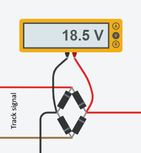
If you want to know what the maximum amplitude (V) is (perhaps to compare different systems?), you need to rectify the power and measure the DC voltage after rectification. You can use an off the shelf rectifier or 4 diodes (such as 1N4001) arranged like this:
Brake modules
Some manufacturers offer what they call brake modules that will stop a digital locomotive in a non-digital manner. It works by rectifying the track current (so that it is DC), and locomotive decoders which support braking modules are designed to slow to a stop when they detect DC current. That tells you that the digital current is not DC, leaving only AC as the alternative (given that there is no 3-phase system).
Other digital systems
In the text above I have described the AC wave form of DCC, but there are also other digital systems, such as the original Märklin digital system. Detailed information on the electrical characteristics are not as readily available as for DCC, but the Märklin (item 0303) book: Model Railroading Digitally Controlled by Georg Fuhs and published in 1988 gives clear evidence that the track signal is AC.
On page 11
...it was decided during the design phase of the Märklin Digital system to limit it to only two "conditions", namely "positive voltage" (approx. +20 volts) and "negative voltage" (approx. - 20 volts)
When describing how the original c80 decoder works on pg. 71 it states:
The c 80 locomotive decoder receives information sent by the Central Unit or Central Control. This information is first checked for frequency. The decoder is able to differentiate conventional operation (50 Hz), information for solenoid accessories (approx. 10 kHz) and information for locomotives (approx. 5 kHz).
DC current does not have a frequency to detect. It goes on though:
The "digital current" is rectified at the entry point to the decoder so that a continuous current for controlling the locomotive motor through the track is available independent of the flow of data. The power supply for the auxiliary function, by comparison, comes only from the negative part of the third rail potential.
So, they rectify (convert from AC to DC) the current, and furthermore they declare that the aux function is only half wave rectified, a clear indication that both positive and negative voltages are present. That means it is AC.
On pg. 73 they discuss what happens if there is DC current on the track:
If DC current is present in the track, the locomotive will function only when there is a positive potential in the third rail. If the potential is negative, this corresponds to the condition "turn on" in the Digital control and results in a quasi "stand by": the locomotive remains at a halt and the auxiliary function is shut off. The information for speed and auxiliary function remain stored, however. As soon as the third rail potential becomes positive again, these stored commands are carried out.
So this conclusively confirms that the Märklin Motorola based digital track current was also AC.
Personal note: In 1989 I visited Georg Fuhs at his residence and demonstrated the program I had written which he tested on an N scale Arnold layout he was building in his basement, and it worked.
Note that unlike DCC, the Märklin Motorola (MM) system encodes 1s using a positive voltage and 0s with a negative voltage. DCC instead makes the duration of both a positive and negative cycle twice as long for a 0 than that of a 1. This means that if you were to keep sampling a voltage directly on a MM system you might see a higher voltage when more 1s are being transmitted than 0s. On a DCC system the ratio of 1s to 0s will make no difference when averaged.
Additional notes
- Amazingly it is possible for both MM and DCC to coexist in the same track. This is achieved by controllers such as the Intellibox, allowing both MM and DCC decoders to run on the same track.
- Many decoders can handle multiple protocols and even analog, switching to whatever style of current they detect.
- If you are still not convinced that digital track signal is a form of AC, place an LED with a 1K Ohm resistor across the two track poles. LEDs can only tolerate power in one direction. They will burn out if AC current is applied or DC is applied in the incorrect polarity. If the LED lights up and stays on, then you have DC or pulsed DC current. This can be confirmed by reversing the LED, switching the polarity. If it then burns out, it confirms that you have DC or pulsed DC power. If an LED burns out no matter what the polarity, then you have AC power.


